
|
|
|
|
2018年12月02日 |
|
|
Projection and transformation matrix in 3D space
A projection is translating an object’s representation from one set of dimension to another. The most common projections are carried out from three to two dimensions. The common types of projection is called planar geometric projections, this kind of projections are projected with straight projectors (a ray from the center of projection to the object) onto a flat plane. In a parallel projection, the projectors are parallel to each other. If you move the center of projection (COP) farther and farther away from the plane of projection, then the projectors become closer and closer parallel, then the projectors can be thought as parallel as the COP move to infinitely. The most common types of projection are called planar geometric projections, this kind of projection the projectors are projected on a projection plane.
Orthographic projections are generated when the projectors are perpendicular to the projection plane. Orthographic projections fall into two major categories:
(1) Orthographic projections
In architecture and engineering drawings both 2D projections plan and elevation projections are important, the dimensions and angles need to be recorded to some scale, so we need the multi-view orthographic projections to render the object, then we can use the orthographic projections. If the projections plane are perpendicular to the principle axis of the object is called as orthographic projections.
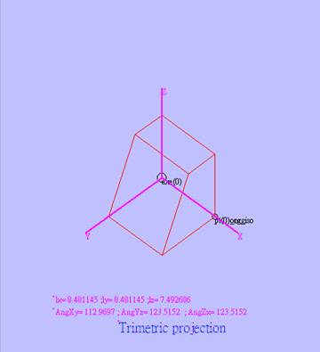
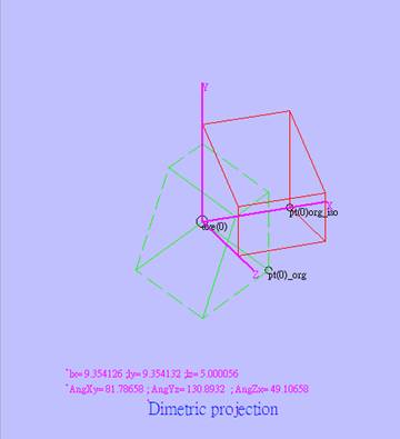
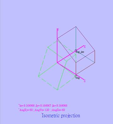
(2)Axonometric projection:
If the projection plane is not perpendicular to a principle axis of the object, so that 3 sides of the object are visible in the projection. This results in a better 3D rendering. If all 3 principle axes of the object make equal angles (lengths) to the projection plane, the projection is called isometric projection. When two axes have equal angles (lengths) to the projection plane, the projection is called dimetric projection. If all angles are different, the projection is called trimetric projection. The trimetric projection can often generate the most realistic 3D simulation, since the projection plane can be placed freely with respect to the object. A problem with axonometric projections is that they sometimes seem to be distorted a little bite.
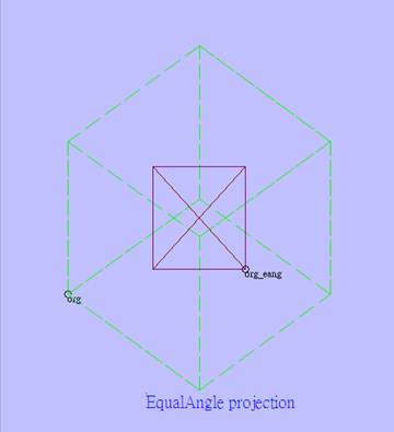
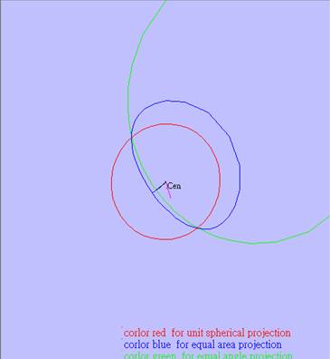
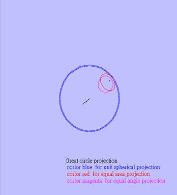
(3)Spherical projection : Most Geologists and Geotechnical Engineers are familiar with the use of Spherical projections , Equal angle and equal area projection, for the presentation and analysis of structural geology data. The two methods of projection have been discussed completely in my web site “chday19.url.tw”.
(4)Matrix transformations :
Multi-view Orthographic projections are the easiest way of object rendering, because they involve only a single matrix operation which sets the either x, y or z equal to 0 depending on the side being viewed. In general, axonometric projections, require 3D matrix operations. A translation, rotation and simpler orthographic projection are added to a projection matrix of one of the multi-view projections. Hereafter, I attached some useful VB 6.0 projection transformation matrix sub program as following:
Public Sub IsomPrjMaker() Dim i As Integer, j As Integer, tIso(0 To 3, 0 To 3) As Single Dim Phi As Single, Theta As Single Phi = 45 * Ra Theta = 35.26439 * Ra Erase tIso() For i = 0 To 3 For j = 0 To 3 tIso(i, j) = 0 Next j Next i tIso(0, 0) = Cos(Phi) tIso(0, 1) = Sin(Phi) * Sin(Theta) tIso(0, 2) = -Sin(Phi) * Cos(Theta)
tIso(1, 0) = 0# tIso(1, 1) = Cos(Theta) tIso(1, 2) = Sin(Theta)
tIso(2, 0) = Sin(Phi) tIso(2, 1) = -Cos(Phi) * Sin(Theta) tIso(2, 2) = Cos(Phi) * Cos(Theta)
tIso(3, 3) = 1# glAxIso = tIso(0, 0) glAyIso = tIso(1, 0) glAzIso = tIso(2, 0) glBxIso = tIso(0, 1) glByIso = tIso(1, 1) glBzIso = tIso(2, 1) glCxIso = tIso(0, 2) glCyIso = tIso(1, 2) glCzIso = tIso(2, 2)
End Sub Public Sub DimetricPrjMaker() Dim i As Integer, j As Integer, tDim(0 To 3, 0 To 3) As Single Dim Phi As Single, Theta As Single Phi = 22.208 * Ra Theta = 20.705 * Ra Erase tDim() For i = 0 To 3 For j = 0 To 3 tDim(i, j) = 0 Next j Next i tDim(0, 0) = Cos(Phi) tDim(0, 1) = Sin(Phi) * Sin(Theta) tDim(0, 2) = -Sin(Phi) * Cos(Theta) tDim(1, 0) = 0# tDim(1, 1) = Cos(Theta) tDim(1, 2) = Sin(Theta) tDim(2, 0) = Sin(Phi) tDim(2, 1) = -Cos(Phi) * Sin(Theta) tDim(2, 2) = Cos(Phi) * Cos(Theta) tDim(3, 3) = 1# glAxDim = tDim(0, 0) glAyDim = tDim(1, 0) glAzDim = tDim(2, 0) glBxDim = tDim(0, 1) glByDim = tDim(1, 1) glBzDim = tDim(2, 1) glCxDim = tDim(0, 2) glCyDim = tDim(1, 2) glCzDim = tDim(2, 2) End Sub
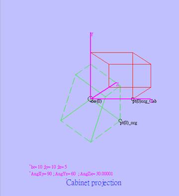
Public Function CabinetPrjMaker(Alph As Single) Dim Sx As Single, Sy As Single, Sz As Single Sx = 1 Sy = 1 Sz = 0.5 Alph = Alph * Ra glAxCab = Sx glAyCab = 0 glAzCab = Sz * Cos(Alph) glBxCab = 0 glByCab = Sy glBzCab = Sz * Sin(Alph) glCxCab = 0 glCyCab = 0 glCzCab = 1 End Function
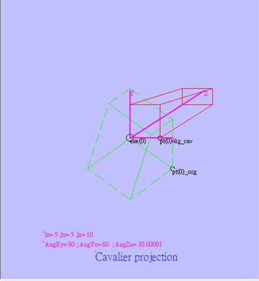
Public Function CavalierPrjMaker(Alph As Single) Dim Sx As Single, Sy As Single, Sz As Single Sx = 0.5 Sy = 0.5 Sz = 1 Alph = Alph * Ra glAxCav = Sx glAyCav = 0 glAzCav = Sz * Cos(Alph) glBxCav = 0 glByCav = Sy glBzCav = Sz * Sin(Alph) glCxCav = 0 glCyCav = 0 glCzCav = 1 End Function
Public Function EqualAnglePrjMaker(z As Single) If z>=0.0 then glAxEang = 1 / (1 +abs(z)) glBxEang = 1 / (1 + abs(z)) else glAxEang = -1 / (1 +abs(z)) glBxEang = -1 / (1 + abs(z)) end if glAyEang = 0 glAzEang = 0 glByEang = 0 glBzEang = 0 End Function
Public Function EqualAreaPrjMaker(z As Single) If z>=0.0 then glAxEang = 1 / Sqr(1 + abs(z)) glBxEang = 1 / Sqr(1 + abs(z)) else glAxEang = -1 / Sqr(1 + abs(z)) glBxEang = -1 / Sqr(1 + abs(z)) end if glAyEang = 0 glAzEang = 0 glByEang = 0 glBzEang = 0 End Function
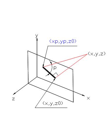
To get the projection point(xp,yp) from 3d point(x,y,z), you can apply the formulas as following: xp=glAx??*x+glAy??*y+glAz??*z ‘here glAx yp=glBx??*x+glBy??*y+glBz??*z Here, glAx?? Can be glAx,glAxIso,glAxCab……………….
|
上次修改此網站的日期: 2018年11月25日